


|
|
|
|
This page contains information about
building and controlling an inexpensive robot.
If you have any questions, please e-mail me:
gary@messagestick.net
The robot described here is based around a '386 SX mother board and some standard ISA bus cards. It is constructed with a car battery for power, a voltage regulator circuit (shown below), and a relay control board which connects to a parallel port on the computer and drives two car windscreen wiper motors to give the robot motion.
I have named the robot here "R4" (pronounced "ar-for", as in "R for robot"). R4's brain is a 386 computer running the Linux operating system. Linux is a free-ware version of Unix: a true multi-tasking system. Source code for the control programs may be down-loaded for your version of R4 (see the software section). Let's now look at the various components of R4...
The chassis has a number of layers. From the top they are:
The computer runs the Linux operating system. This is a free-ware version of Unix which can be obtained on CD from most technical book shops for about $40. I'm using "Slackware Version 3.0" which uses the Linux kernel version 2.0. This is not critical. You could probably run all the same programs under DOS if you wanted to recompile them. Although you would have a bit of work getting some of the low-level interface code working.
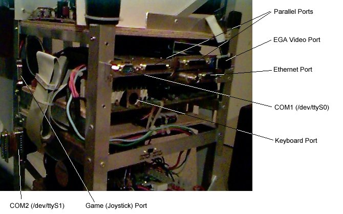
I use the LAN (ethernet) card to communicate with the command interpreter module via telnet. It was also used to initially load Linux via NFS (I also use Linux on my desk-top PC to write and compile the code).
The photgraph (58KB) shows a close-up of the external ports on the computer. You will notice that the I/O cards are lying horizontal (the same as the mother board) instead of at right-angles to the mother board. I used an EISA-bus extender board (about $3) to do this and save a bit of vertical space.
A second battery is used to power the computer and disk drives. This is a 12V 7.2Ah sealed lead-acid battery which also feeds a 5VDC regulator circuit for the computer and other TTL-based circuitry. This battery feeds from the main battery via 12 ohms of resistance and a rectifier. This allows me to connect the charger only to the car battery and still recharge both batteries without the motors and screen draining vital computer and disk power. I can get anything up to 3 hours use from the batteries before they need recharging.
The last battery (low current) is used as -12VDC for the computer. This battery is only necessary if you want to use the serial ports on the computer. The positive battery terminal is connected to the computer ground rail so the negative terminal can deliver -12VDC. I use COM2 (/dev/ttyS1 under Linux) as a terminal port for logging into the system via a dumb terminal (or PC running a terminal emulator). I connected this battery with its own power switch as it is not often used.
The power regulator can be built from anything which delivers at least 2 amps at 5VDC. Have a look at the schematic and vero-board layout to see what I built. This power supply is designed to supply 5 volts DC (regulated) at up to 10 amps. This should be sufficient for 3 or 4 PCs to allow for distributing the computing needs via a local (in-chassis) ethernet.
Here is the parts list for power supply shown:
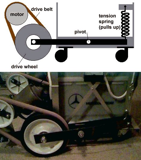
The Drive Wheels
The wheels used are 2 x 150mm solid rubber trolley wheels (available from most hardware stores). The motors I used are standard 12-volt car windscreen-wiper motors. I could have used very expensive stepper-motors but I decided not to for 2 reasons: (1) widscreen-wiper motors are a lot cheeper ($10 each from auto wreckers) and (2) stepper motors are only useful for very fine movements if you have a reference position. If the wheels slip on a surface, you loose your reference and need some way of re-calibrating. I opted to later add this recalibration ability (probably some sonar or optical device) and use it to constantly monitor (and correct) R4's direction and position using that.
The motors drive the wheels via a drive belt (actually a rubber sewer-pipe seal). The pully wheel used on the motor is a 70mm trolley wheel with the rubber tyre removed. Have a look at the picture (53KB).
 The motors have 3 wires comming from them: 1 for ground and 2 for +12 volts (forward
and reverse directions). Each of these leads is switch by a relay (2 for each
motor). It is important to not apply power to both the 12-volt
leads at once. This is achieved by controlling the relay switches with some
simple logic circuitry as shown in the diagram here. You can drive the inputs,
A and B, directly off lines from the parallel printer port (or any other TTL port).
Each output can be used to drive the base of a transistor which, in turn, can either
drive the base of a power switching semiconductor or the coil of a relay switch.
You can have a look at the vero-board layout (19KB) for
the circuit that I built.
The motors have 3 wires comming from them: 1 for ground and 2 for +12 volts (forward
and reverse directions). Each of these leads is switch by a relay (2 for each
motor). It is important to not apply power to both the 12-volt
leads at once. This is achieved by controlling the relay switches with some
simple logic circuitry as shown in the diagram here. You can drive the inputs,
A and B, directly off lines from the parallel printer port (or any other TTL port).
Each output can be used to drive the base of a transistor which, in turn, can either
drive the base of a power switching semiconductor or the coil of a relay switch.
You can have a look at the vero-board layout (19KB) for
the circuit that I built.
Arm Control
(not built yet)